Electrical Resistivity Tomograph (ERT)
An Arduino-based instrument that images subsurface soil by injecting current into the ground and measuring millivolt potentials. Validated on 1D, expanding to 2D.
Problem
Commercial resistivity rigs start around $20,000, and most of that cost is measurement electronics rather than anything conceptually hard. The physics is just Ohm’s law applied to a the ground. The difficulty is entirely in the instrument cost. The signal is also relatively small (tens of millivolts riding on a common-mode voltage volts higher). The earth’s own natural potentials like telluric currents swamp most DC reading, and contact resistance can be pretty large and variable.
How it was solved
Bipolar injection. An L298N H-bridge alternates polarity as a low-frequency square wave. Each half-cycle is measured separately and differenced: steady offsets appear in both and cancel exactly, while the real signal flips sign and doubles.
Differential sensing. An AD620 instrumentation amplifier rejects the common-mode voltage, presents an input impedance high enough not to disturb what it measures, and lifts millivolts into ADC range. Common-mode leakage measured about 20 µV referred to input.
Measured current, not assumed. A 1 kΩ shunt read on an ADS1115 turned out to be independently verifies current instead of calculated via the supply voltage due to the voltage of the earth also playing a component in the resistance.
Four electrodes and stacking. The potential pair draws no current, so electrode contact resistance never enters the answer. Twenty cycles averaged per reading cut noise by roughly √N.
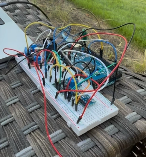
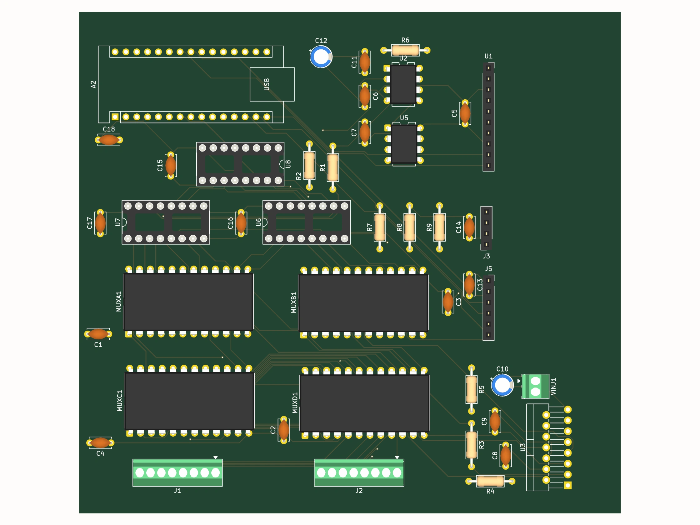
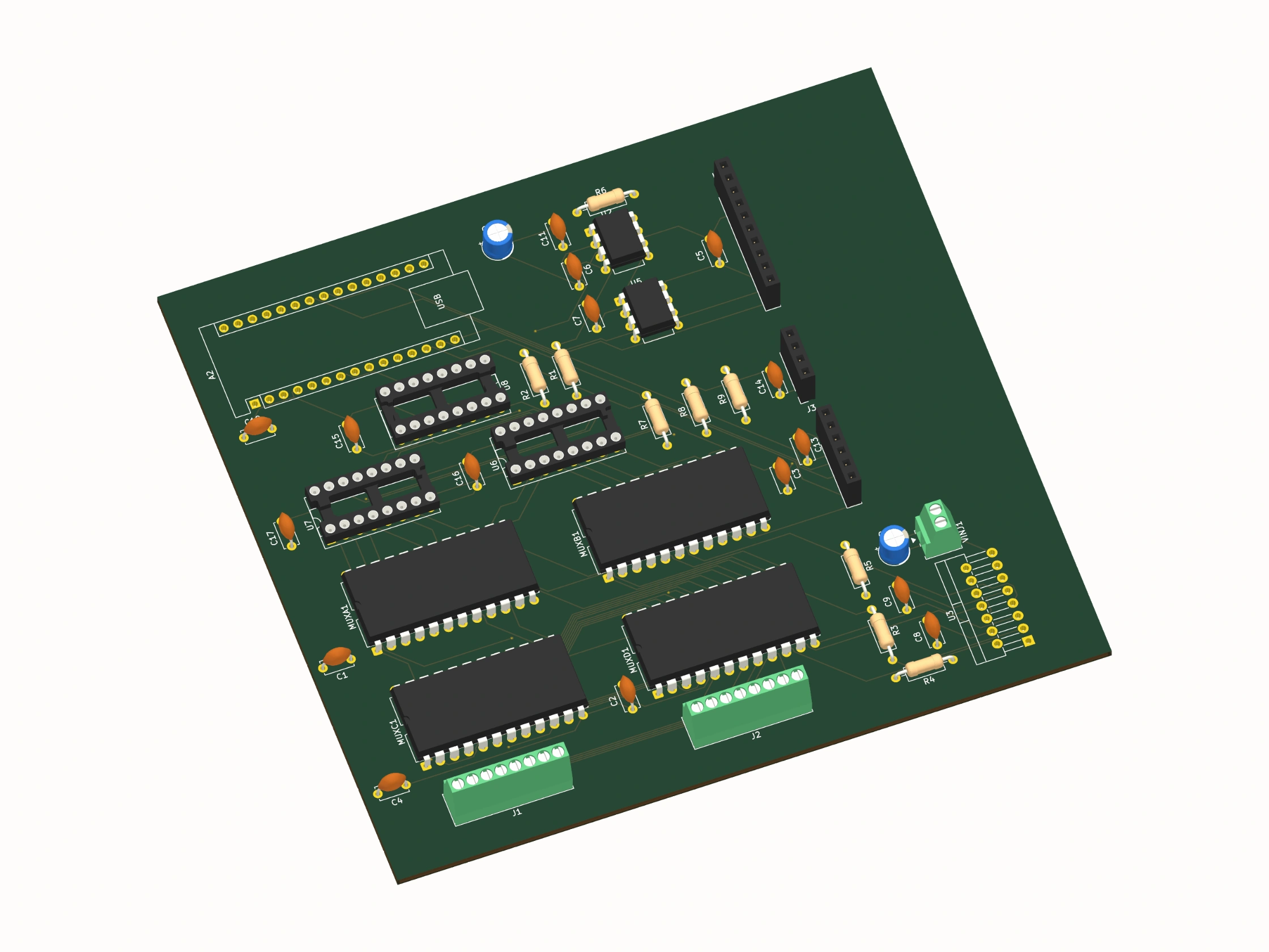
One board instead of breadboards. The 2D version needs 16 electrodes, so the array moves onto a PCB: 44 parts, four 16-channel multiplexers, and 10 kΩ protection on every ADC input. An autorouter round trip returned 686 violations at first with my arduino mega setup so a nano was used in the pcb design.
Results
Bench validation against a known 100 Ω resistor reads 98.6 Ω, 1.4% error, with nothing in the chain assumed: gain, chain resistance, and injection voltage all measured directly rather than taken from labels.
First field measurement, four electrodes at 0.5 m Wenner spacing in Georgia soil: 71 Ω·m, successive readings agreeing within 1.5%, squarely in range for moist clay-rich soil.
Figured out steel potential electrodes polarize during measurment so survey length needs to be capped before drift becomes a false gradient. Four ADS1115s died due to current spikes and shorting.
The board is designed and ordered. Everything passed the tests, but I didn’t have time to test it out before school because I was rushing to finish petbot.
Figures